2-bit Multiplexer
- TYelectronics
- Jul 26, 2023
- 1 min read
Now this is a fun one.
How to make a multiplexer.
I was trying to design an address selector when I by mistake discovered I had made a multiplexer, needless to say that I was surprised. It was a 4 bit MUX (shown at the bottom) but I wanted to test my design to see if it actually worked so I thought I would design one and put it to the test, but a 4-bit variant required a lot of BJT around 80 and I though that is too many just for a test. So I changed the design to only be 2-bit which require a lot less.
Here is the schematic which I designed using my 4-bit MUX as reference.

The first column inverts the input, the second is a selection of gate that only become true when a certain input combination is entered, and the third column is the data output which is either High or Low depending on the Data Pin.
Now lets put it to the test.
On the left is the 2-bit input selector.
In the middle is the 2-bit MUX.
On the right is 8-bit Buffered LED (visualizer)

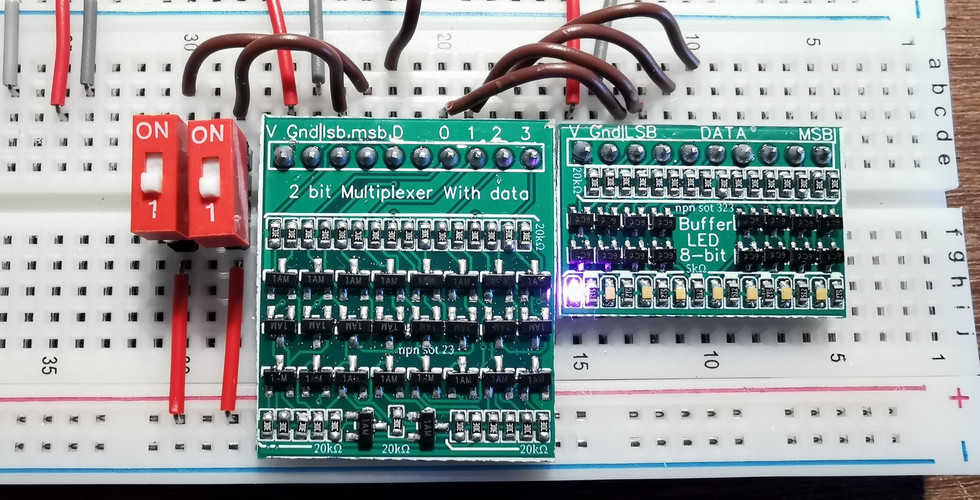


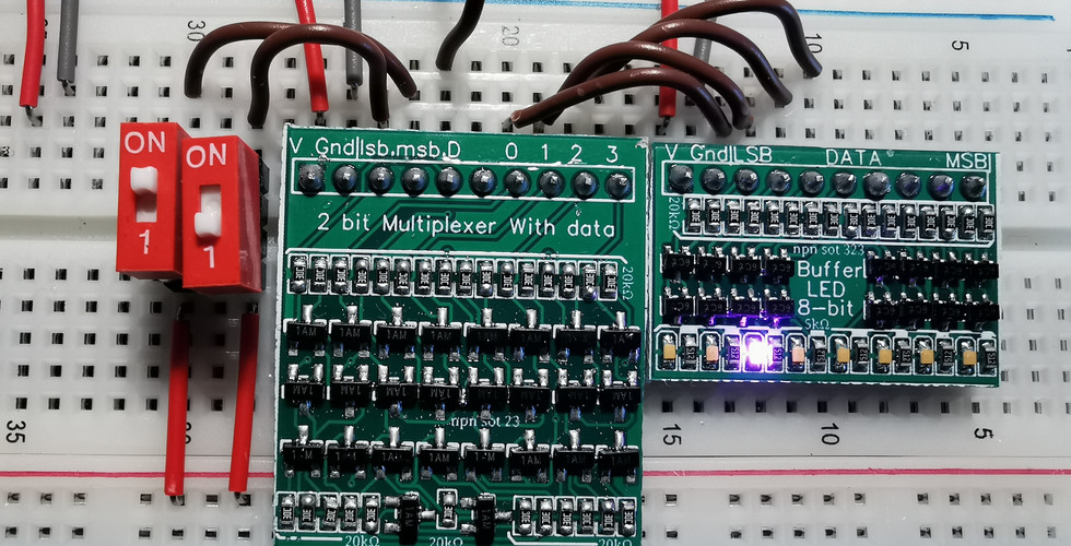


We have set date pin High.
If input 00 output 0 goes High.
If input 01 output 1 goes High.
If input 10 output 2 goes High.
If input 11 output 3 goes High.
(you can scroll the photos sideways)
And as you can see it works. Again I was very surprised.
Here is the 4-bit Logic Diagram (This does not have a data pin) with a confusing 2-bit Diagram at the bottom.

Comments