Electricity capture: Wave Energy
- TYelectronics
- Jun 5, 2023
- 6 min read
So, as we need more renewable energy I thought it would be an interesting thought experiment to take a first principles approach in designing a mechanism the captures energy from the oscillating aspect of waves.
To start with we need some design parameters.
1: To be no invasive to the local environment.
2: Relatively simple design i.e. it can be mass manufactured effectively.
3: The internal components can be adjusted to suit the local condition.
4: Has the ability to be self sufficient i.e. un-tethered from land/seabed. (I need to think about this aspect a bit more as the could be some cool features that could be added, I'll write about it at the end probably).
5: Doesn't look really ugly.
Ok we have a list now we need to start throwing some ideas around. What are other ways we generate electricity? Generators use combustion to apply a force to a leaver which rotates and electric motors. Wind turbines/Water wheels use external force applied to the end of a leaver to rotate and electric motor. What can we take away from these few examples, it seams like a lot of things use rotation to create electricity so that must be a good starting point.
Now we need to figure out what a wave has to offer. The basic property of a wave is the fact that the surface rises and descends nearly all the time at not cost to us (that I know of), there are also currents the flow in all different directions at different times (but I think we wont talk about that for now). So to simplify it, we have an UP and DOWN motion that we should be able to make use of.
The thing that springs to mind is a heavy mass which is suspended by springs attached to the inside of a floating container. In this case there is just one spring to make it a bit easier to draw.

In stage 1 the float has just ridden down the back a wave and is now in the trough (we'll call the the bottom transition point) it is now stationary for a split second, but the mass inside still has some momentum and will continue moving down until the spring has enough upwards force to overcome its mass x acceleration (9.81 m/s²) and bring the mass to a stand still. But by that time the float is already starting to ride up the next wave.

In Stage 2 the float has ridden half way up the wave and in doing so, it is pulling up on the spring which is now storing that upwards motion as Elastic potential energy and then when it is fully stretched out it starts to pull up the mass as well.

In Stage 3 the float has just arrived at the peak of the wave (we'll call it the top transition point) and is stationary for a split second again. And due to the spring having stored Elastic potential energy it continues to pull the mass upwards, until the springs energy is depleted. And the cycle starts over again (I know I missed the inverted version of stage two but I'm sure its clear enough.)

I drew a graph of what you might expect to see if you plotted the movement of the float and the mass, so that you could get a rough idea of what is going on. As you can see the Mass is always lagging behind the Float and that offset can be modified by changing the spring strength and the Mass's weight. The gradient of the lines represent the acceleration values for both objects and the Mass line also represents the level of compression(UP) and de-compression(DOWN) of the spring. This graph is also assuming that the waves are oscillating that harmonic frequency of the Spring/Mass system.
What we have just unveiled are two forms of energy "Elastic potential energy" and "Gravitational potential energy". Ok so how do we extract energy from those two sources. One solution is to use hydraulic fluid to transport the combined energy into another single form of energy storage (Elastic potential energy), which can be monitored and controlled to be able to output a more stable energy supply which intern can spin a "water wheel"
So lets look at some of the components we would for a system like this.

Variable hydraulic pressure
High hydraulic pressure
Low hydraulic pressure
Moving parts
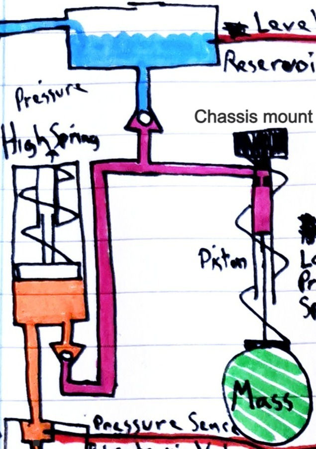
The Chassis mount mounts directly to the Floats roof.
The pressure hydraulic fluid is stored in a reservoir at the top and can only let fluid out the valve when there is a negative differential pressure between the Reservoir and the variable pressure hydraulic fluid.
On the right is a piston with an inlet for the variable pressure hydraulic fluid as well as the spring we have been talking about in the above section.
On the left we have the second piston and spring with a valve which only lets variable pressure hydraulic fluid into the piston with a positive differential pressure between the high pressure hydraulic fluid and the variable pressure hydraulic fluid.
How it works.
When the float goes up, the Mass lags behind and increases the volume in the piston which lowers the pressure (of the variable pressure hydraulic fluid) and when it becomes lower then the reservoir's pressure it sucks out fluid from the reservoir.
Now we have more fluid in the variable pressure hydraulic fluid section.
When the float starts to go down, the Mass is still lagging behind which means the volume in the piston is decreasing which increases the pressure of the variable pressure hydraulic fluid.
When the pressure in the variable pressure hydraulic fluid is greater then the pressure in the high pressure hydraulic fluid the fluid will be pushed into the second piston.
This prosses continues until the pressure that has built up in the high pressure hydraulic fluid is greater then the pressure that the Mass/Wave system can produce. At this point an electronic valve will open at the output of the second piston.

On the far top-left is the electronic output valve.
Below that is a water wheels style mechanism that creates rotation from pressure.
On the right is an electric motor.
How it works.
When enough pressure has build up in the second piston, a signal opens the electronics valve which forces hydraulic fluid into a water wheel, which then rotates, and through some ratio enlargement it spins the electric motor. This then outputs voltage at the motors terminals, that gets sent to the inverter to create a DC voltage. Back to the hydraulic fluid, once it is out the back of the water wheel it is low pressure and can be pumped back up to the reservoir. And when there is no more pressure in the high pressure hydraulic fluid the electronic valve closes and the cycle starts again.
Here is the full layout, which shows how the electricity is capture and either stored in batteries on sent over power lines onto the land.

This method look pretty cool but I came up with another method which look a bit more simple but maybe not as efficient (I don't know).
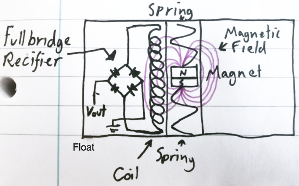
In this version there is a magnet instead of a "Mass" but it acts in the same way in that it lags behind the movement of the float. This means the magnet as well as it's magnetic field is able to move up and down relative to the coil thus inducing AC current which can be put through a Full Bridge Rectifier, to out put a DC voltage.
This voltage could then be manipulated and stored in the same battery circuit as the hydraulic variant.
Moving on the design of the float and how it can be self sufficient.
There are a couple of things I was thinking.
It has multiple propellers to keep it located in the same position using GPS as it would not be able to be anchored because that would stop the oscillating movement.
It has a vision/sonar system for object avoidance. (Like if a boat did not see it, it would just move out of the way).
It has tanks like a submarine so that it can raise or lower its buoyance.
Now for the really cool concept. Image there was a fleet of 100 (or any number) untethered autonomous floats, when one of them has completely charged its onboard battery it can navigate itself to a sea bed docking station where it can unload its charge via seabed cables to a land based battery which can then supply the grid. And when it has done that it undocks and goes back to it's original location to start charging its batteries again.
Just an Idea.
Comments